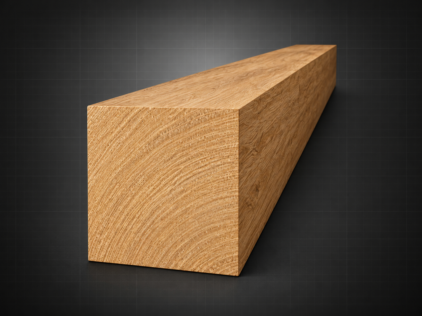
Plain
Flat, unmodified face.
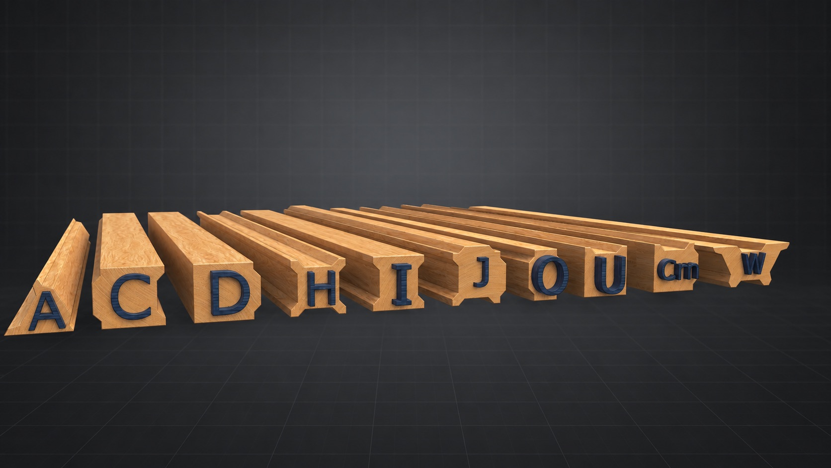
I-Wood system reference
A modular family of wood profiles organized around three nominal size classes and a common Hill-and-Valley geometry.
The I-Wood interface concept
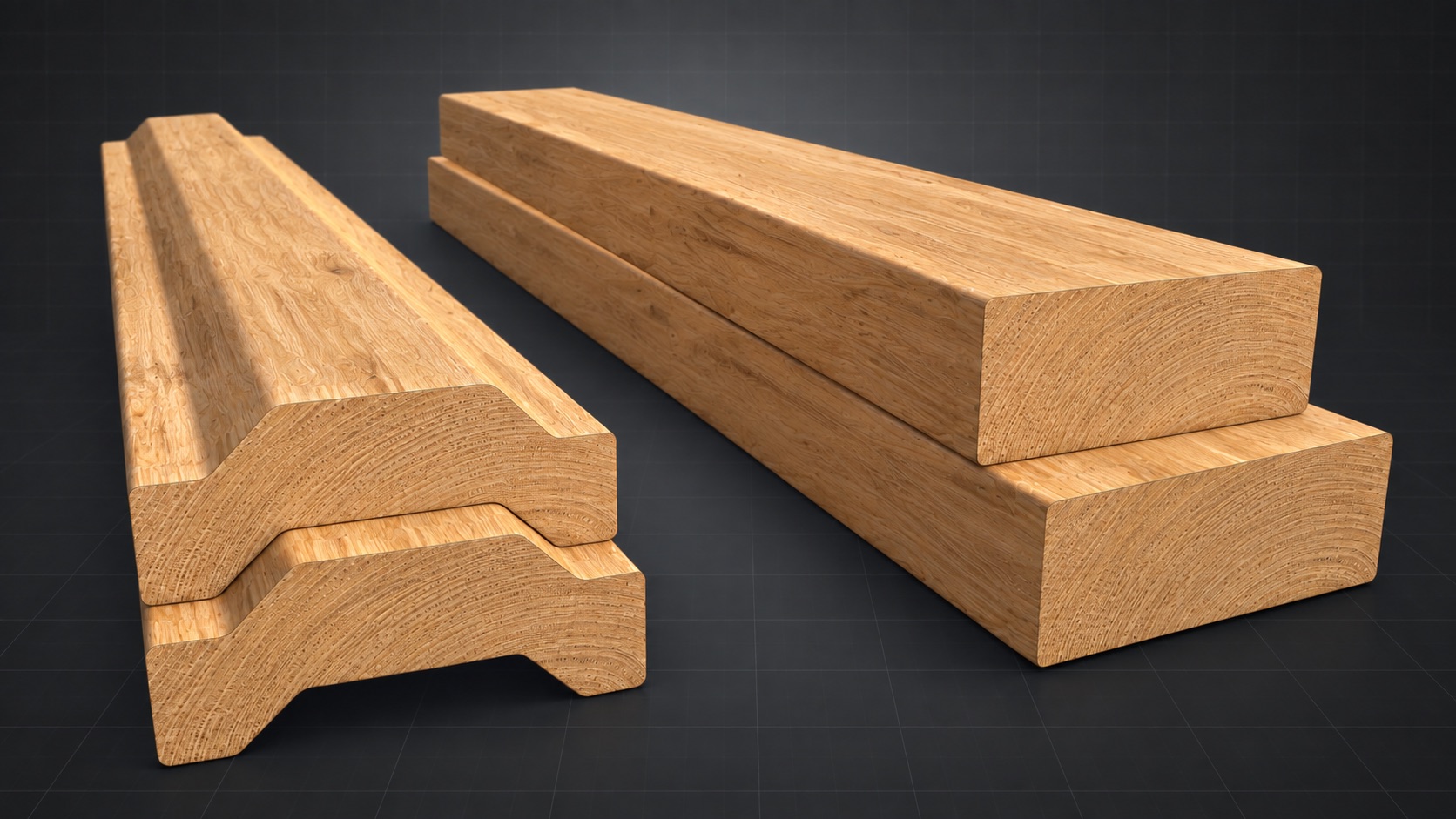
What distinguishes I-Wood is the addition of two complementary surface geometries—Hill and Valley—to an otherwise conventional wood component. These shallow profiles transform timber from raw stock into a repeatable part of a joint, allowing adjoining components to locate, engage and align through their own geometry.
The principle is related to a tongue-and-groove joint, but incorporates designed-in tolerance along the profiled surfaces. This provides limited accommodation for the natural dimensional movement of wood caused by changing moisture conditions while maintaining positive registration between components.
Because the Hills and Valleys are deliberately shallow, they can read as architectural detailing rather than purely functional machining. The profiles can be produced using relatively simple router tooling, from small workshops through to economical production-scale manufacturing.
When assembled, the complementary angled surfaces guide the components toward their shared centre. This self-centering action improves alignment, while engagement across several profiled faces distributes forces through the joint and contributes to a secure mechanical connection.
Hill and Valley surfaces interlock and self-align.
Flat, unmodified face.
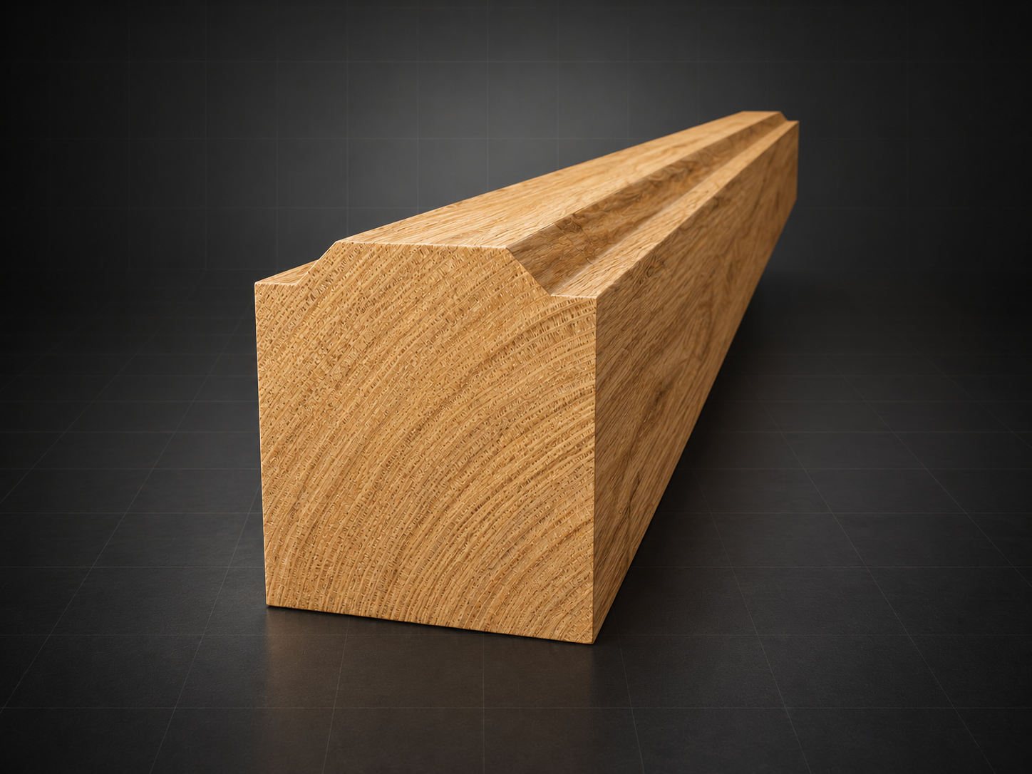
Raised profile intended to mate with a Valley.
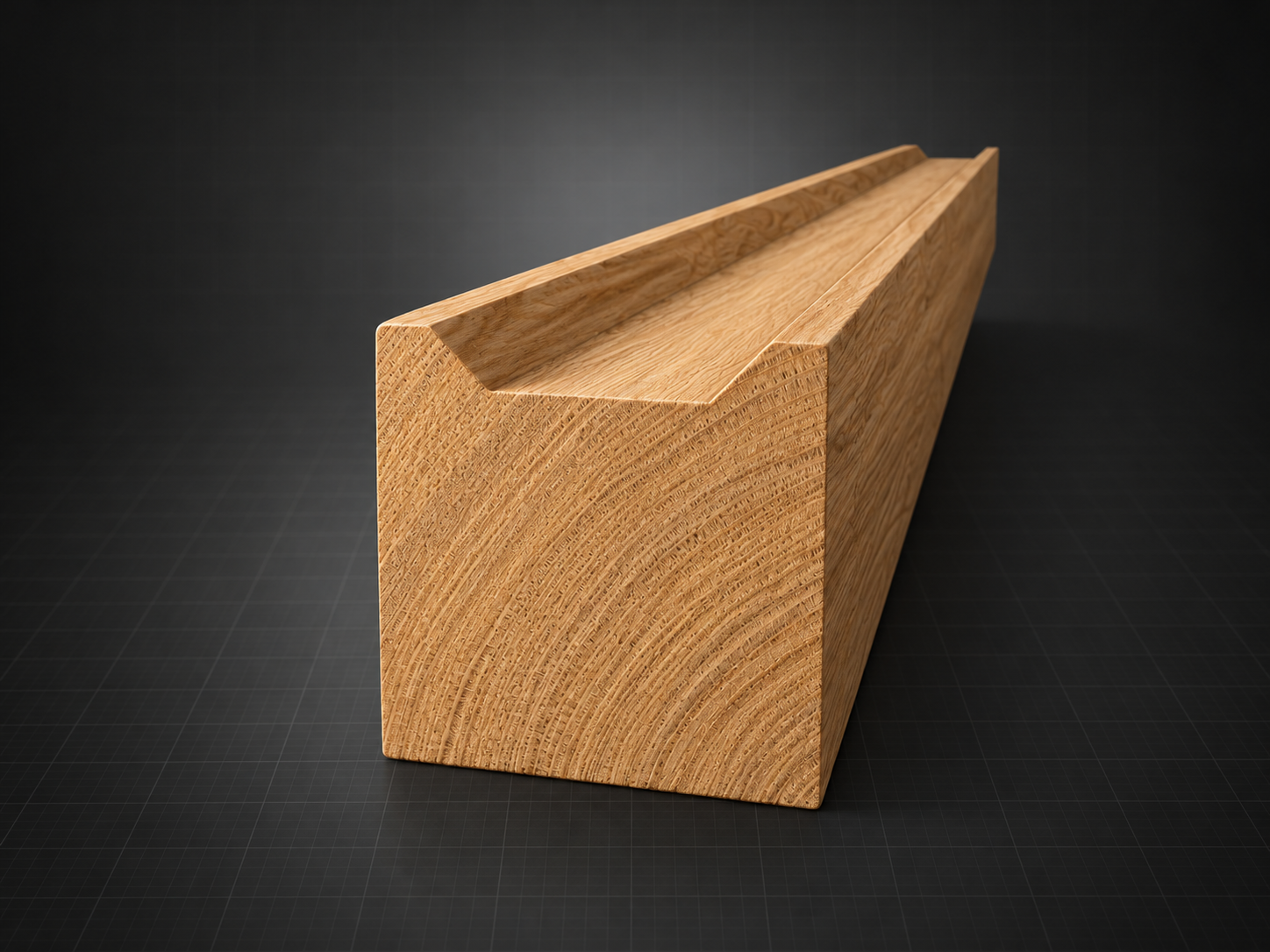
Recessed profile intended to mate with a Hill.
The geometric foundation
The standard continues with a proportional rule set. Every size class scales from the same Hill-and-Valley width, depth, and side-angle relationships.
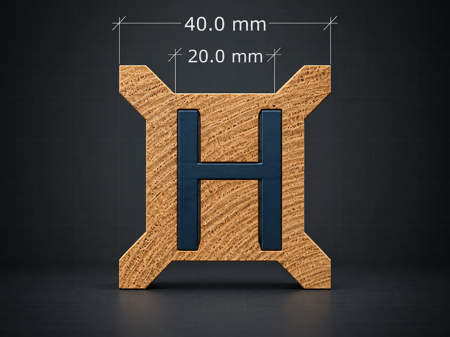
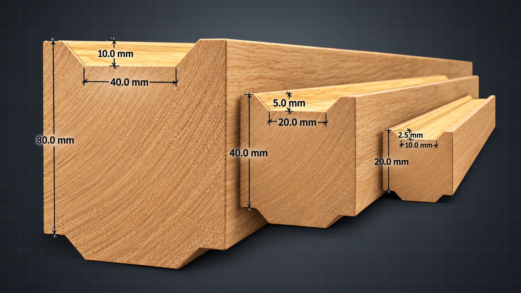
In this Medium-class example, every Hill and Valley is half the 40 mm component width: 20 mm.
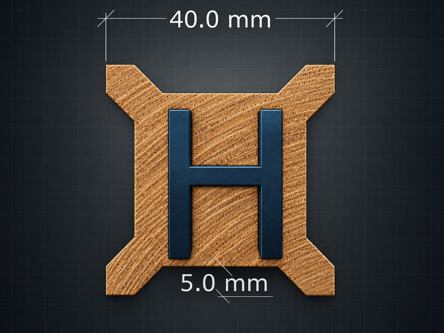
The same 40 mm component uses a 5 mm Hill and Valley depth—one eighth of its width.
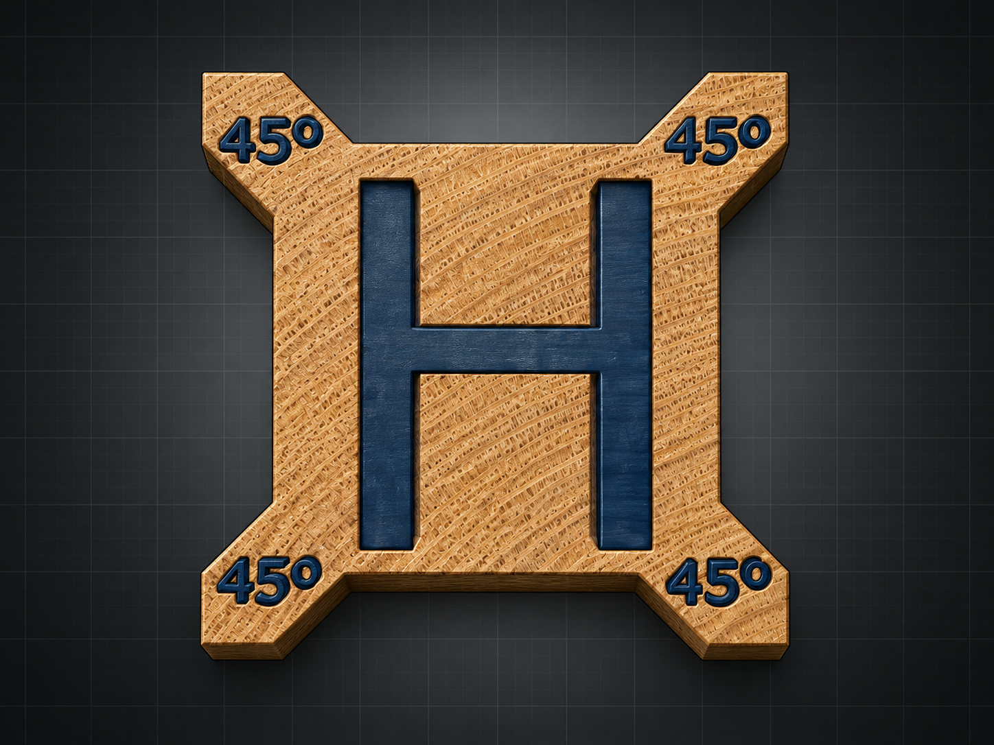
Each sloping side of every Hill and Valley uses the same 45° geometry.
Three size classes
The dimensioned view shows how the 20 mm, 40 mm, and 80 mm profiles scale together and permit selected components to interface across sizes.
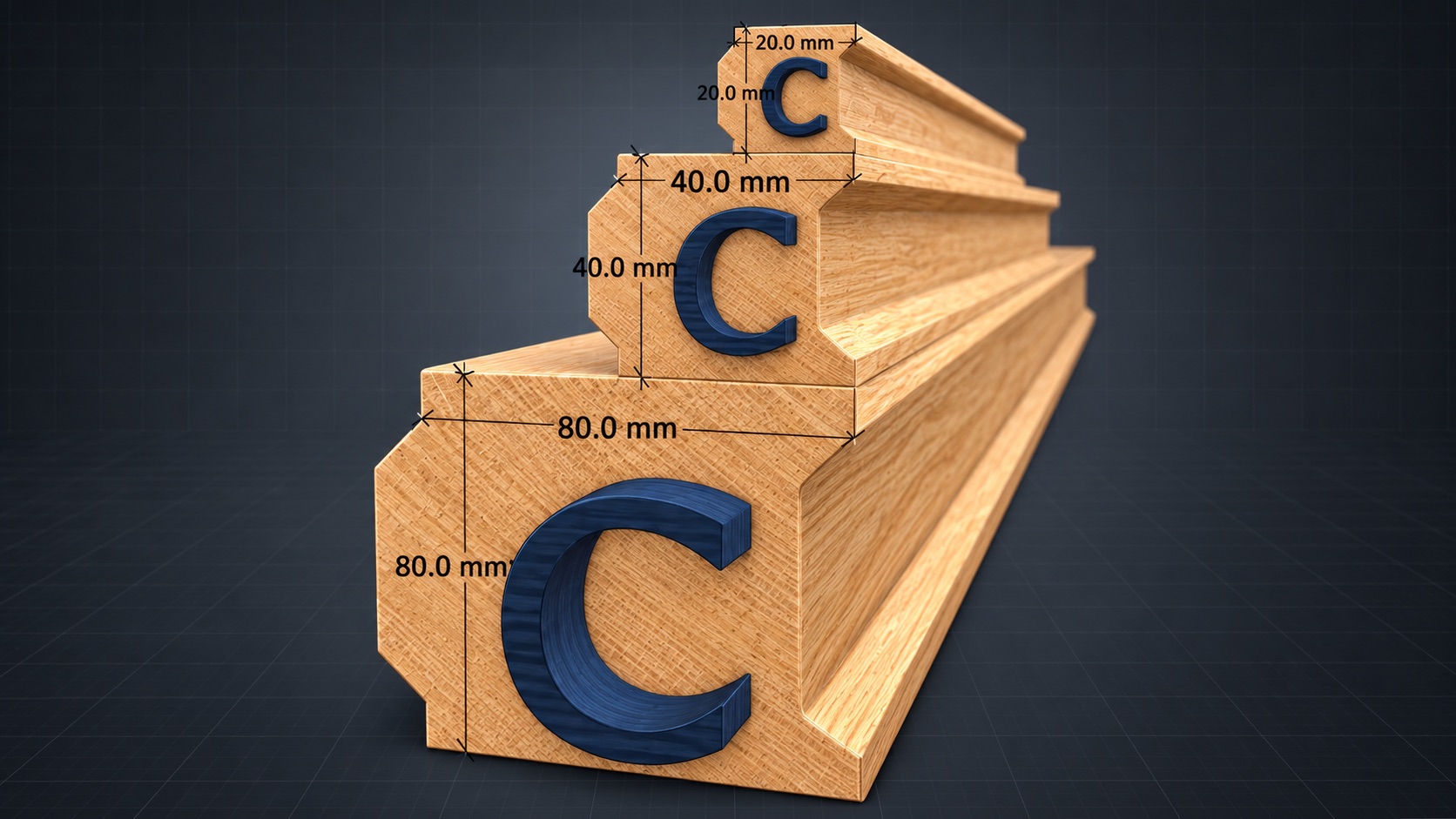
For I-Wood, 20 mm = 3/4 in, 40 mm = 1 1/2 in, and 80 mm = 3 in. The Hill-and-Valley fit is designed to accommodate the small stock difference between the two systems.
| Code | Metric | Imperial |
|---|---|---|
| IW-S | 20 mm | 3/4 in |
| IW-M | 40 mm | 1 1/2 in |
| IW-L | 80 mm | 3 in |
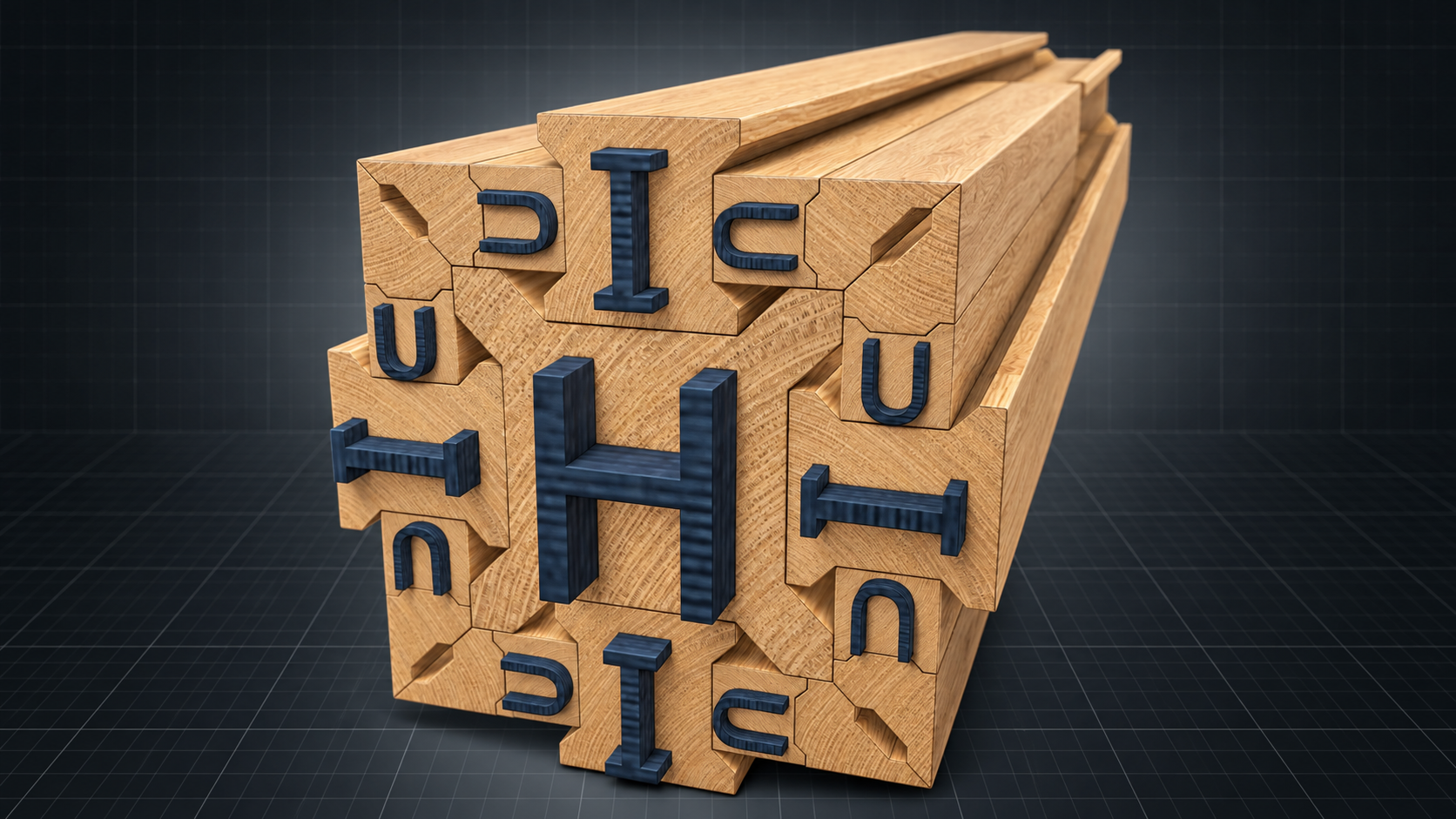
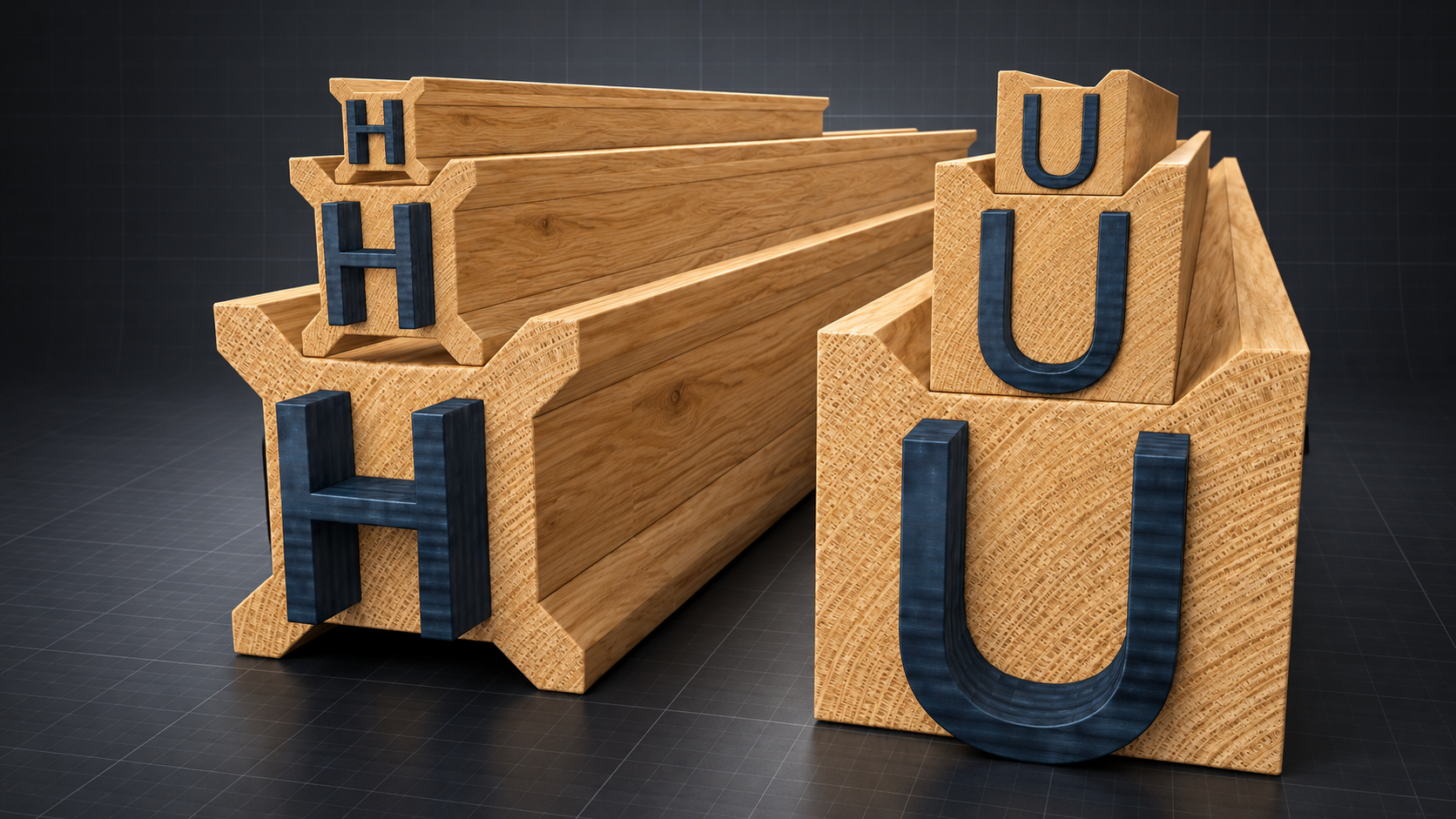
Cross-size Valley registration
Because every Valley is one half of its component width, the system creates two exact cross-size relationships. A 20 mm Small component matches the 20 mm Valley of a 40 mm Medium component. A 40 mm Medium component matches the 40 mm Valley of an 80 mm Large component.
This lets selected components from adjacent size classes seat laterally within the same geometric system, extending alignment and assembly options without introducing a separate interface standard.
Groove geometry
| Size | Component width | Hill / Valley width | Hill / Valley depth |
|---|---|---|---|
| IW-S | 20 | 10 | 2.5 |
| IW-M | 40 | 20 | 5 |
| IW-L | 80 | 40 | 10 |
All values shown in millimetres. All Hill and Valley side angles are 45 degrees. This dimensional progression also demonstrates cross-scale compatibility.
Profile catalogue
Each code identifies one profile. The catalogue uses supplied dimensioned end-view drawings so shape, scale, and Hill-and-Valley geometry can be read together.
Uniform scaling doubles every linear dimension from Small to Medium, then doubles it again from Medium to Large. One dimensioned profile drawing can therefore define the same profile in all three standard sizes.
A profile may also be extended along one principal axis without enlarging the other. Each mating face keeps the Hill-and-Valley proportions assigned to that face, preserving system compatibility while changing only the required width or height.
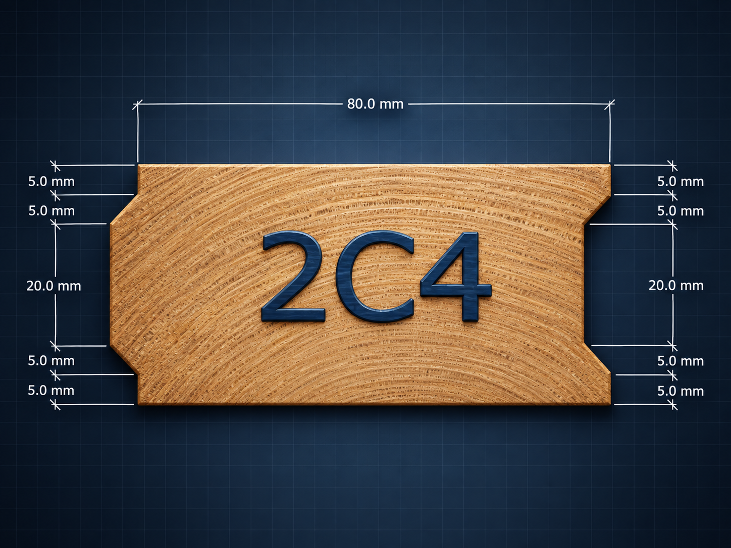
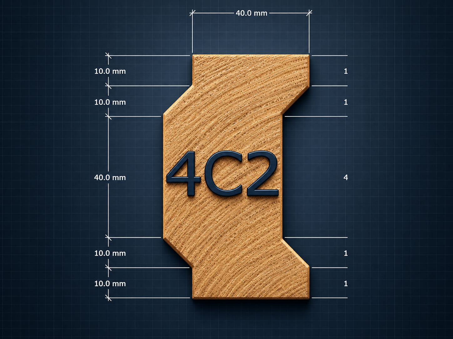
The drawings below show the most common profiles in the IW-M medium size class, with a nominal 40 mm component width. The proportional rules above define the corresponding IW-S and IW-L versions; separate drawings are only needed for directional variants. Select any drawing to inspect its dimensions.
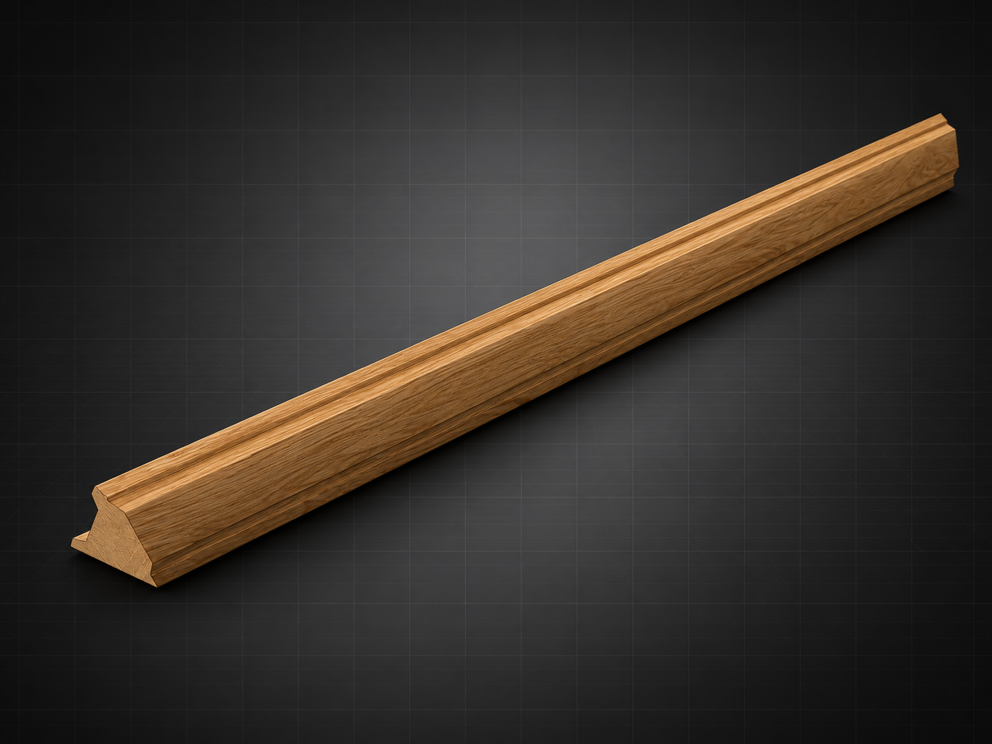
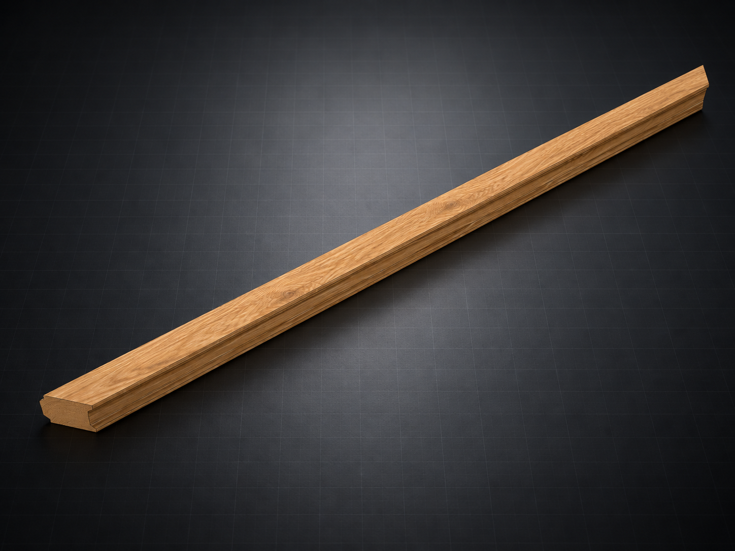
Every component code reads from left to right in the same four-part order: profile, size class, finished length, and end treatment. Hyphens separate the profile-and-size identifier from the length and end treatment.
CC profileMMedium size class120Length in centimetresSSSquare ends at both endsCM-120-SS · Profile + Size – Length – End treatment
These finished components demonstrate how the identification code appears across different profile, length, and end-treatment combinations.
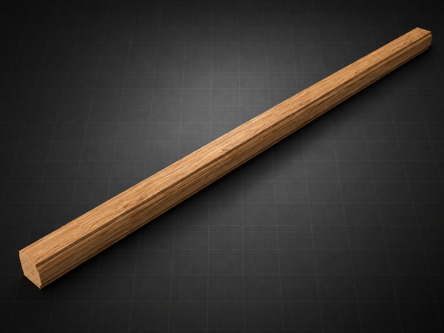
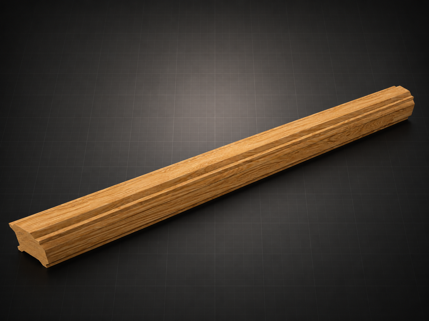
Manufacturing basis
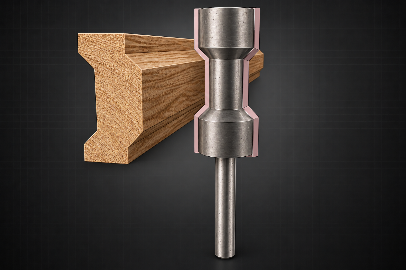
Size stock for the selected component, shape, and surface treatment. The recommended standard length is 1200 mm, approximately 4 ft.
Additional blank material: 2.5 mm, 5 mm, or 10 mm for IW-S, IW-M, or IW-L.
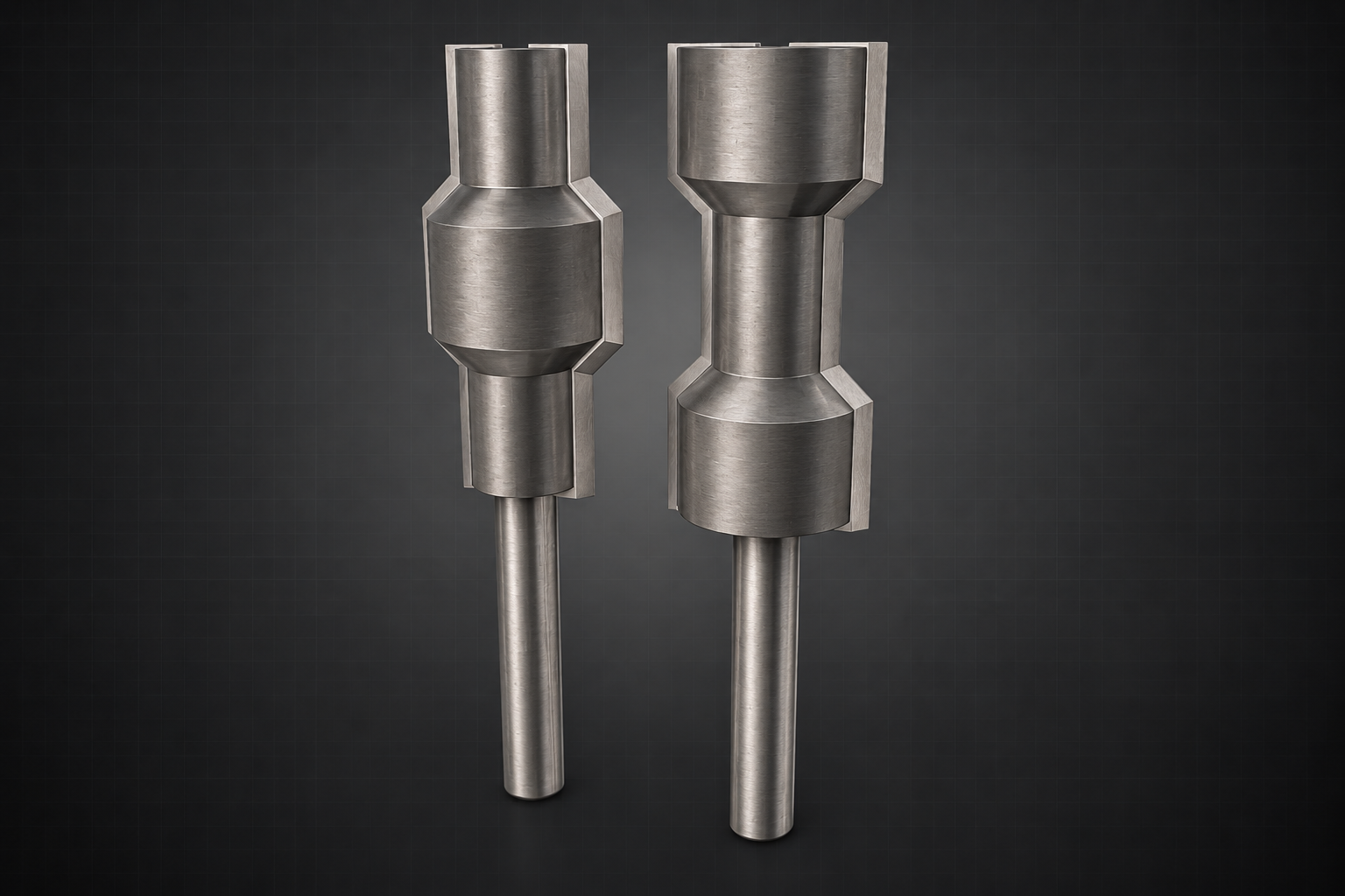
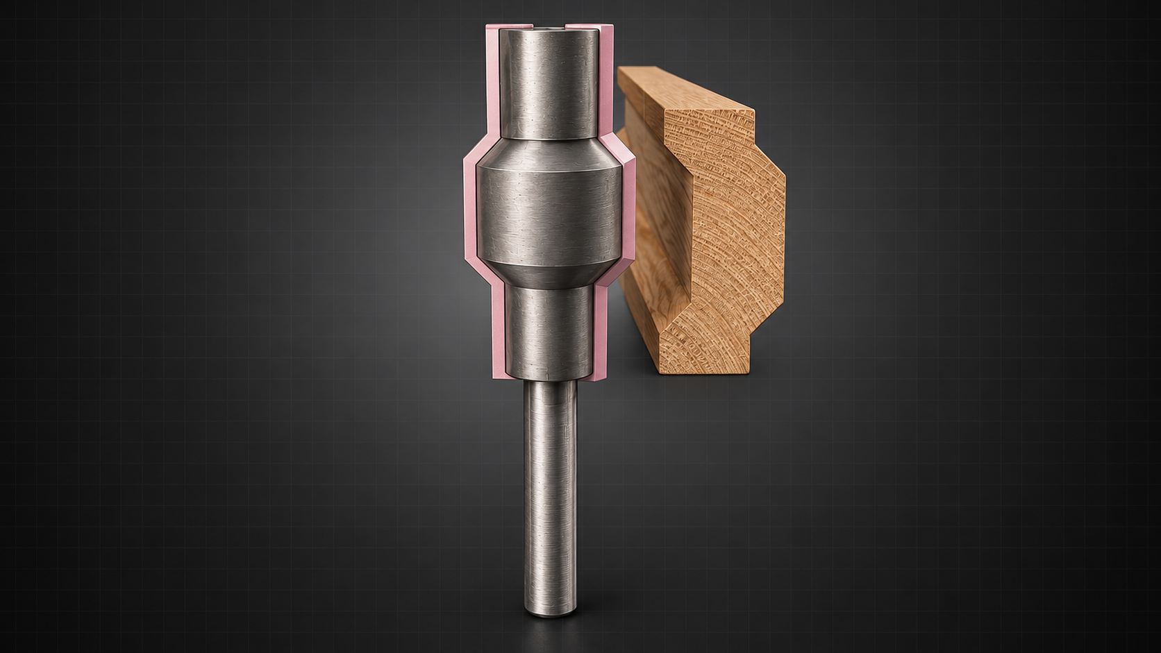
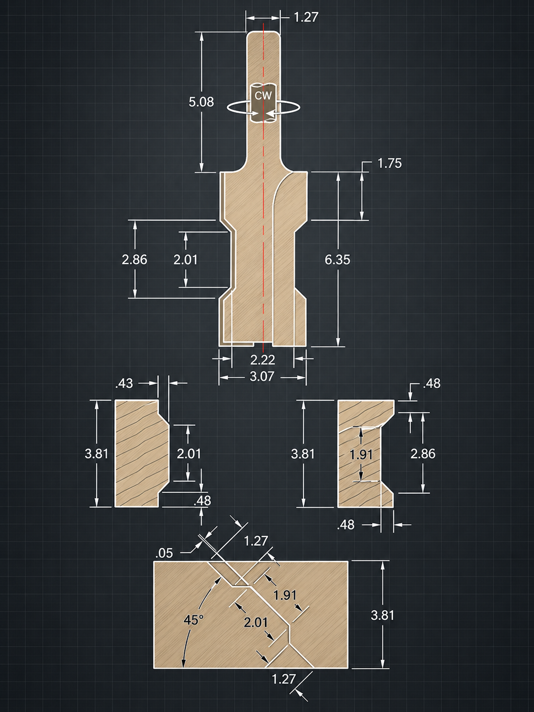
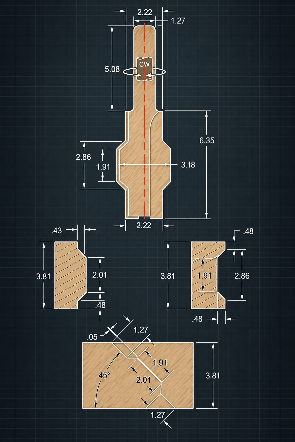
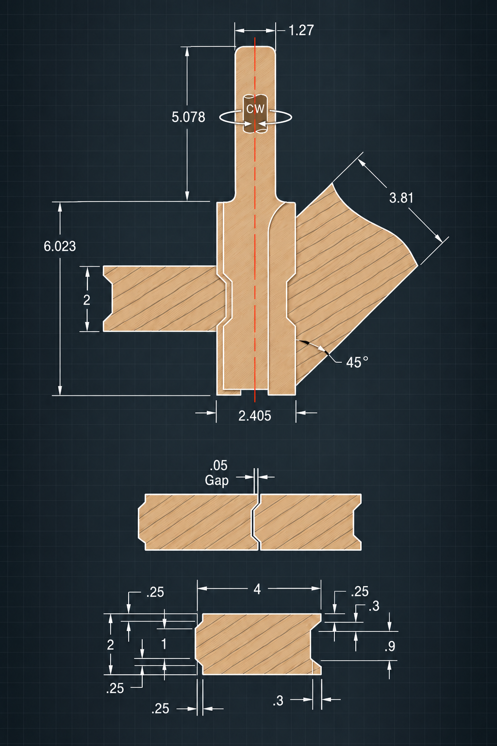
The routing bits reproduce the Hill-and-Valley dimensions shown in the profile drawing. The supplied diagrams document 45-degree routing, Hill-bit, and Valley-bit geometry below.
At a 45-degree angle, the cutting path across the component is longer than it would be in a straight, square cut. The extended cutting edge ensures that enough of the knife remains in contact to cut completely across the component in one continuous pass.
When the workpiece centre aligns with the router-bit centre, the intended routed profile is produced.
Adaptable workshop tooling
I-Wood cutting and drilling jigs use the dedicated Jig profile as a configurable locating body. By setting dimension X to the target workpiece, the same jig principle can be adapted to hold virtually any I-Wood profile securely and repeatably.
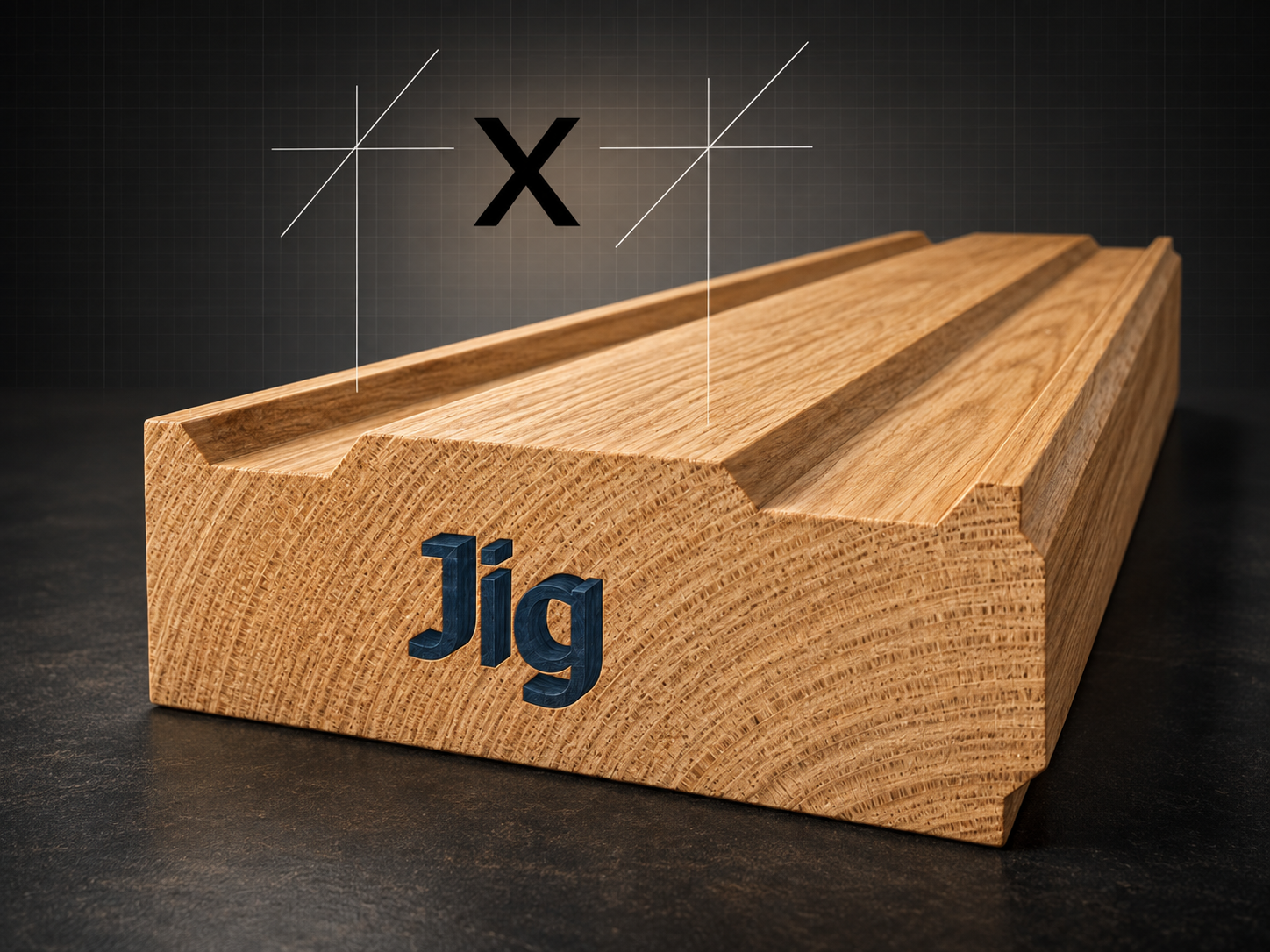
System principle
The Jig profile provides the body of the fixture. Changing dimension X changes the receiving space without changing the basic locating principle, allowing purpose-built jigs to be produced for different I-Wood sizes and profile shapes.
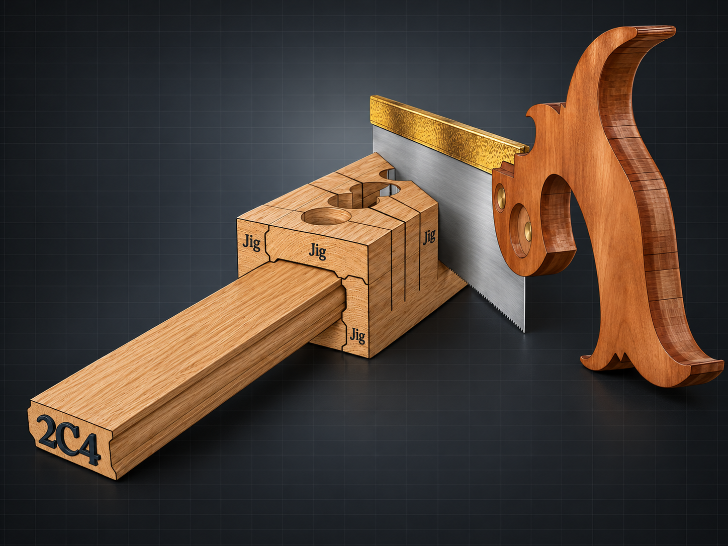
Cutting jig
The workpiece is seated in the jig and the saw runs through the selected guide slot. Prepared slots establish repeatable cuts at 90°, 22.5°, 30°, and 45°, while the Jig profile holds the component in registration and constrains the blade path.
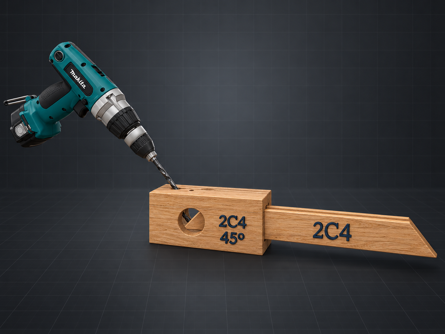
Drilling jig
The drill bit follows a prepared guide hole in the jig body, controlling its entry point and drilling direction relative to the workpiece. A drilling jig can be configured with guides at 90°, 22.5°, 30°, and 45°, then sized through dimension X to suit the required I-Wood profile.
Both jig types separate setup from repetition: profile selection and dimension X establish the fit; the prepared slot or guide hole establishes the tool path.
Jig assembly
The dedicated Jig profile is repeated and rotated around the work zone. Its shaped faces establish how adjoining members meet, while the enclosed opening becomes the receiving channel for the component and its guided operation.
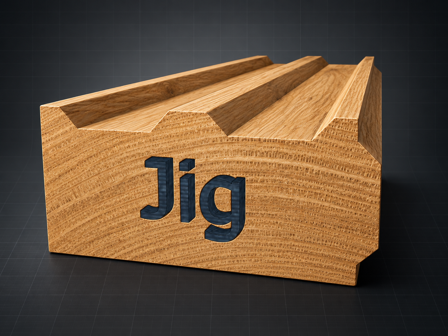
Each side of the fixture is derived from the same purpose-built profile. Repetition keeps the locating geometry consistent around the assembly.
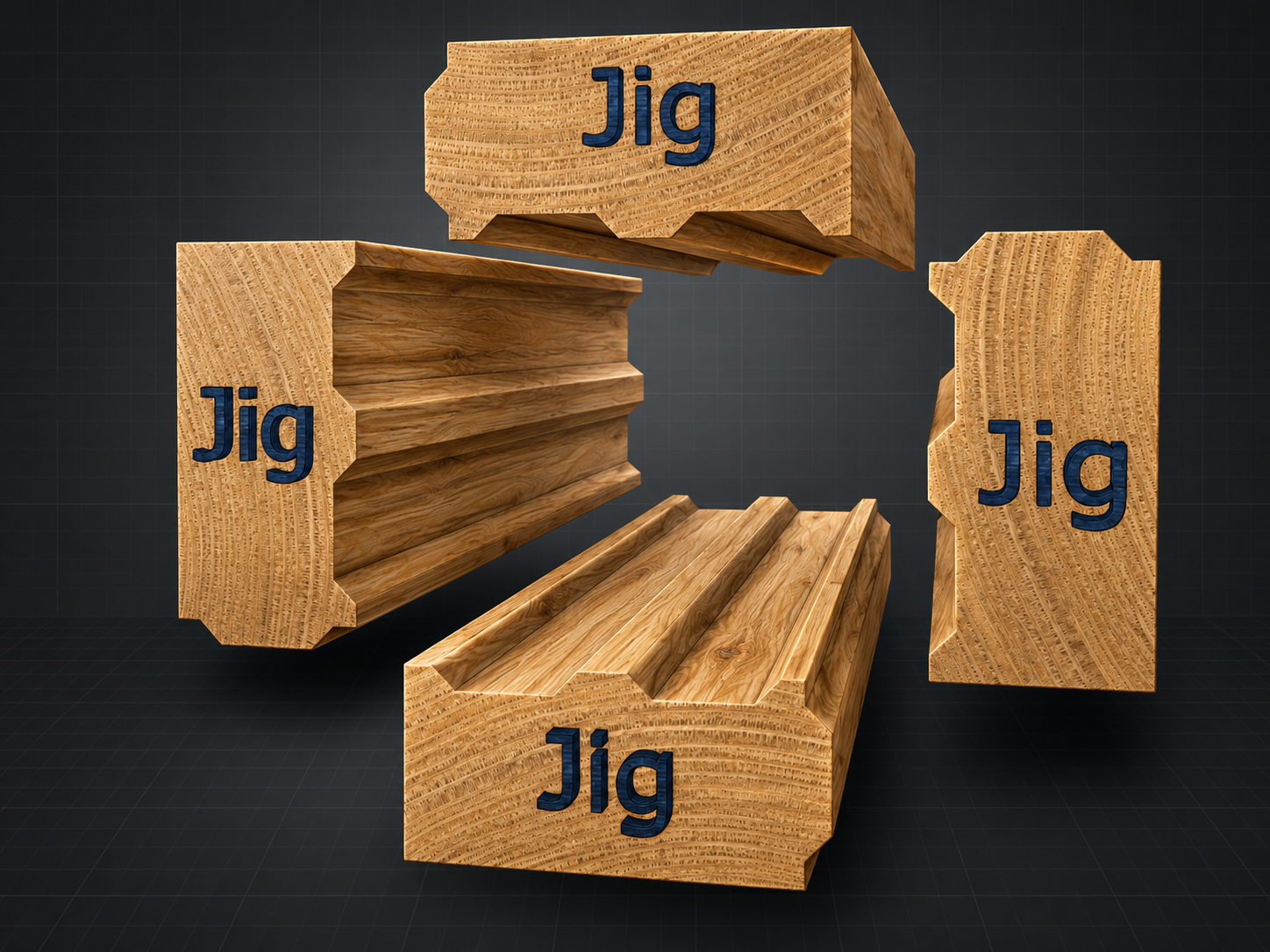
The profiles are rotated into their required sides so the shaped edges approach one another and the central working space remains open.
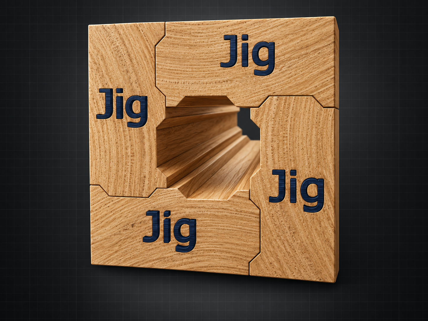
With the four members brought together, the outer frame provides the fixture body and the centre opening defines the controlled receiving channel.
Closed-form assemblies
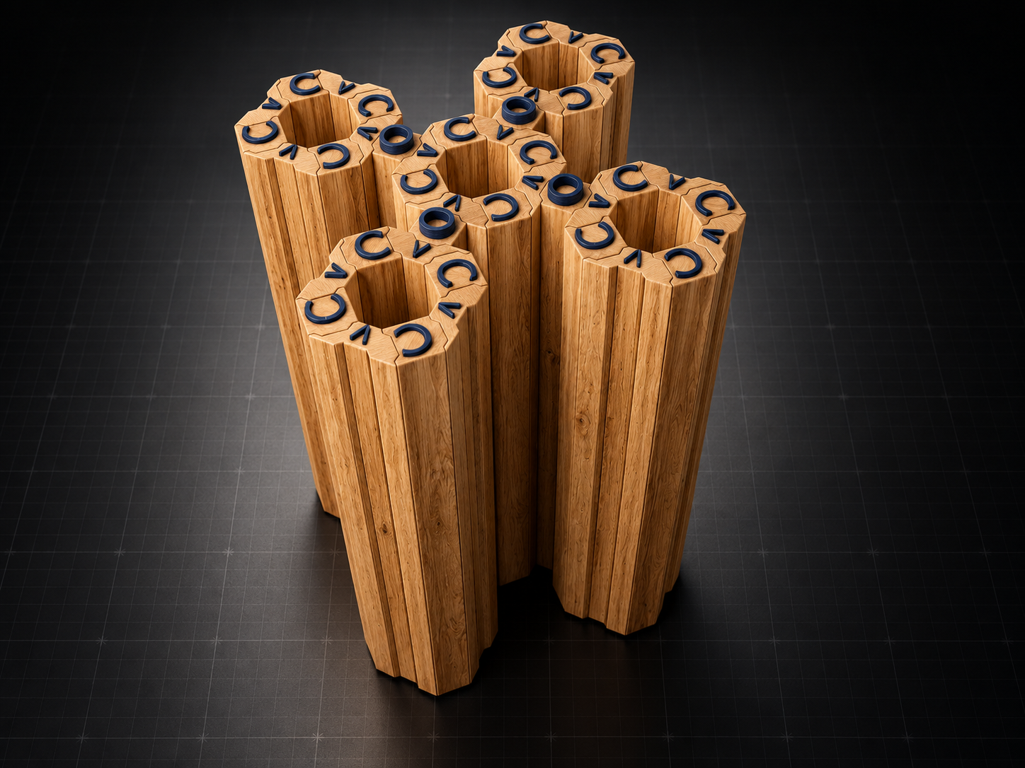
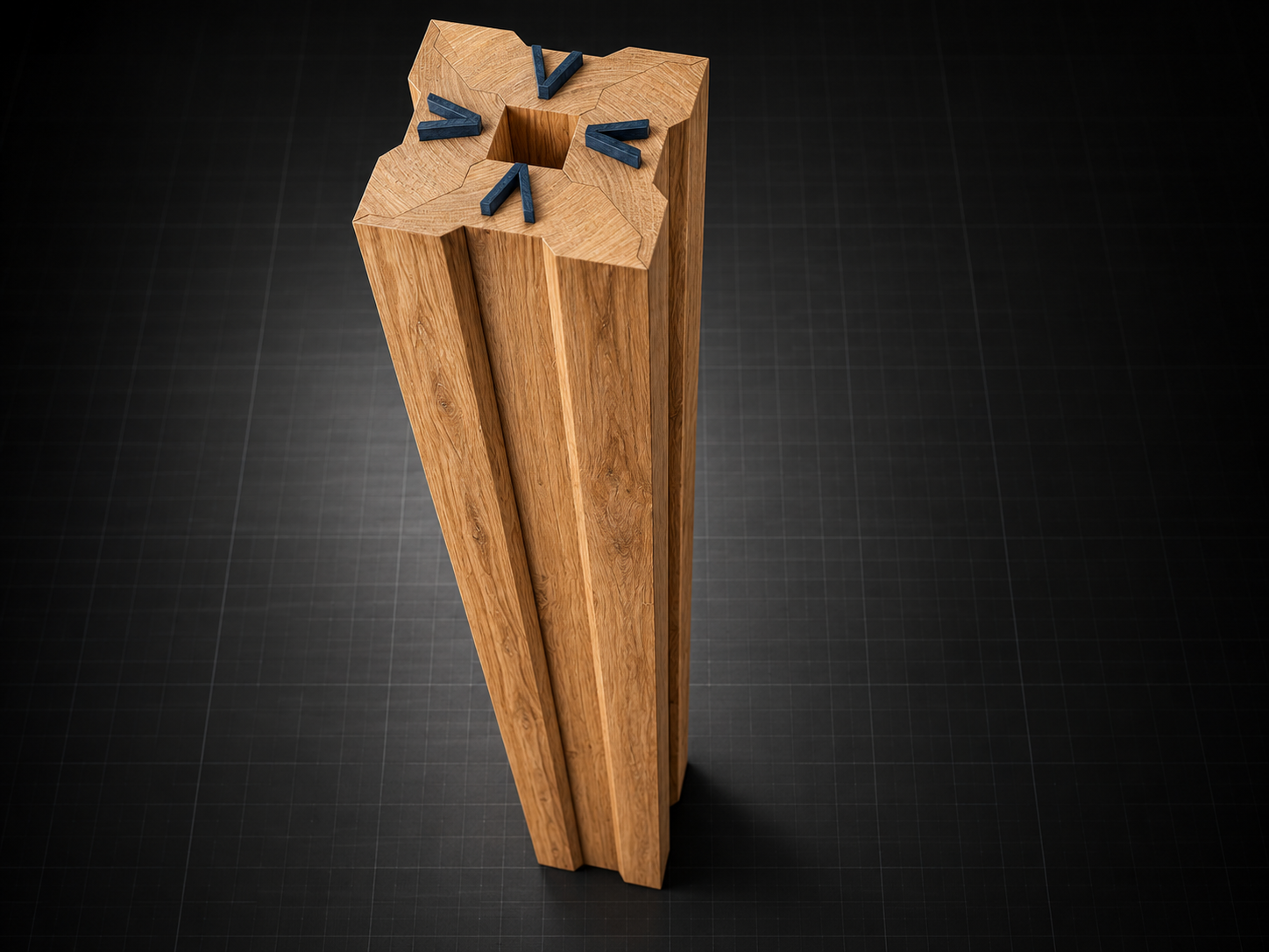
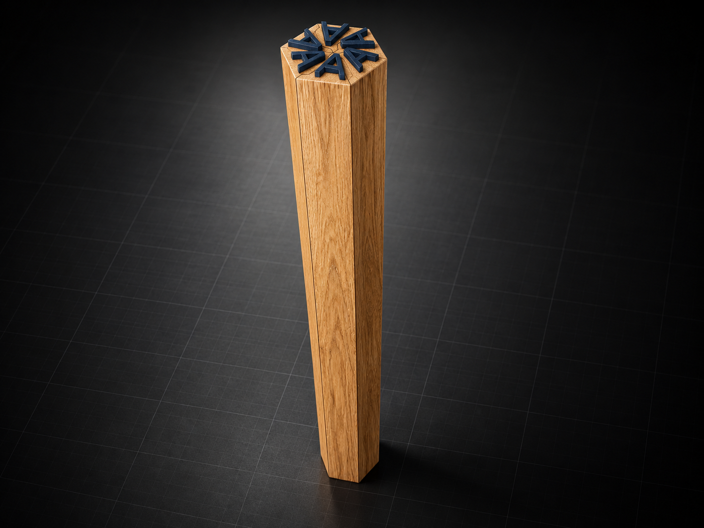
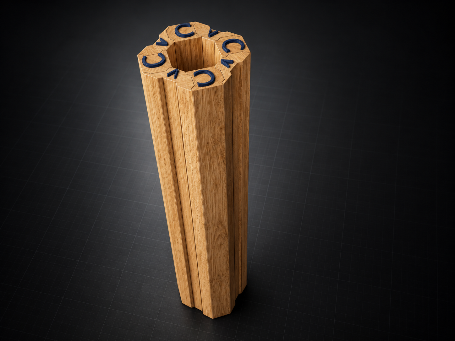
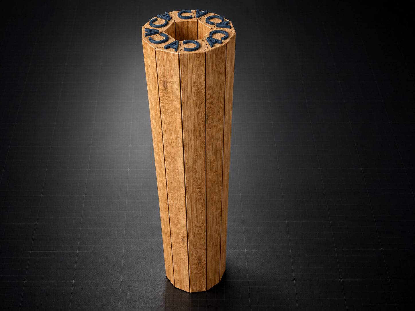
Hill-and-Valley profiles can be repeated and rotated around a shared centreline. As each Hill registers with the adjoining Valley, the individual members close into square, hexagonal, octagonal, and related polygonal sections.
How the geometry closes
Each longitudinal edge forms part of the same complementary interface. When the members are brought together in sequence, their mating faces locate one another and establish the perimeter of the finished assembly.
Potential applications
These assemblies can inform pillars, posts, table legs, lamp columns, hollow decorative casings, and beam-like components. The geometry defines how the parts locate and close; wall thickness, reinforcement, loading, fastening, and code compliance must be engineered for the intended application and region.
Development status